ENGINEERING GUIDE · DESALINATION ENERGY RECOVERY
Reuse pressure.
Reduce pumping duty.
Energy recovery captures useful hydraulic pressure from the SWRO concentrate stream. Its real value depends on the complete plant balance—not a generic savings claim.
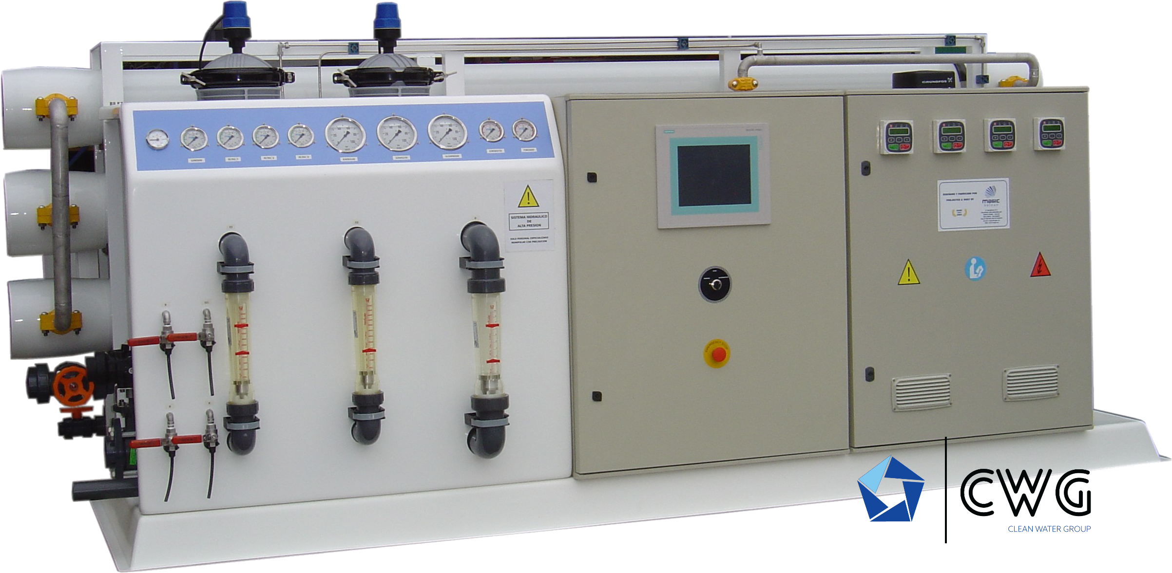
SWRO energy recovery returns useful concentrate pressure to the desalination process.
The device reduces the new pressure duty that must be supplied by pumping. The result must be evaluated at the same verified feed, permeate, concentrate and operating condition.
PRESSURE PATH
Energy remains in the concentrate after separation.
The membrane consumes no energy by itself; the process requires pressure and flow. Energy recovery changes how much fresh pumping input is needed to maintain the approved design point.
Pressurise feed
The high-pressure section raises seawater to the membrane operating duty confirmed by the project design.
Produce permeate
Part of the feed crosses the membrane while salts and retained constituents remain in the concentrate stream.
Preserve pressure
Concentrate leaves the membrane train with hydraulic pressure that would otherwise be dissipated.
Transfer useful energy
An approved recovery device transfers or converts part of that pressure for reuse in the SWRO process.
DEVICE ROUTES
Match the recovery principle to the hydraulic duty.
Technology names alone do not select the device. Review the full operating envelope, integration, materials, controllability and service model.
Explore energy technologyIsobaric pressure transfer
Transfers pressure directly between the concentrate and a feed-water stream while keeping the hydraulic circuits controlled.
VERIFYFlow balance, mixing, pressure losses, booster duty, materials, control and service strategy.Turbine or turbocharger route
Converts concentrate pressure into rotating energy that supports a pump shaft or boosts feed pressure.
VERIFYOperating range, hydraulic matching, controllability, efficiency at duty points and maintainability.No dedicated recovery device
A valid project option where scale, operating profile, complexity or lifecycle economics do not justify the added system.
VERIFYWhole-plant energy demand, runtime, tariff, maintenance capacity and future operating case.SELECTION INPUTS
Six connected decisions define practical value.
Change one input and the preferred equipment, control or economic result may also change.
Feed and concentrate balance
Use the approved production and recovery basis, not nominal permeate capacity alone.
Available hydraulic duty
Review membrane pressure, system losses, device operating range and pressure-control strategy.
Annual operating profile
Hours, load variation, seasonal shutdowns and availability determine how often savings can occur.
Electricity and lifecycle cost
Use the actual tariff, capital difference, maintenance, replacement and financing assumptions.
Operator and maintenance capability
Access, spares, training and response time influence the practical value of the selected device.
Controls and battery limits
Define pumps, valves, bypasses, instruments, interlocks and the surrounding plant interfaces.
COMPARE THE SAME WATER DUTY
A savings claim is valid only when the baseline is equal.
Compare alternatives at the same required permeate production, source condition, recovery basis, product-water duty and availability. Include all pumps, boosters, pretreatment, post-treatment, auxiliaries and controls inside the defined electrical boundary.
LIFECYCLE ECONOMICS
Lower pumping duty is only one side of the decision.
A transparent model makes every assumption visible and keeps equipment scope, operating case and commercial basis aligned.
| Factor | Include in the comparison | Avoid |
|---|---|---|
| Electrical consumption | Measured or vendor-confirmed whole-plant power at the compared duty | Generic kWh/m³ copied from another plant |
| Operating profile | Annual hours, seasonal load, turndown, starts and planned downtime | Assuming continuous full-load operation |
| Capital scope | Device, booster duty, piping, controls, commissioning and integration | Comparing the recovery device price alone |
| Maintenance | Planned service, wear parts, spares, labour and access | Treating recovered pressure as maintenance-free |
| Availability | Bypass philosophy, redundancy, failure response and production impact | Ignoring shared-system dependencies |
| Commercial basis | Tariff, currency, tax, delivery, financing and analysis period | Presenting one payback as universally valid |
VERIFIED SEAMASTER SWRO ROUTES
Evaluate recovery at the correct plant scale.
Capacity positions the platform. Final energy-recovery equipment and performance follow the approved hydraulic and lifecycle review.
DESAL-SWRO PM / PM-C
62.5–1,250 L/hCompact catalog seawater systemsEnergy recovery is evaluated from the selected configuration and actual operating case; it is not claimed as universal compact-system scope.
Explore platformDESAL-SWRO XL · ENGINEERED
36–600 m³/dayProject-engineered seawater plantsThe continuous engineering envelope can integrate project-specific high-pressure pumping, energy recovery, parallel trains and controls.
Explore platformBOX DESAL SWRO
100–1,200 m³/dayFactory-integrated containerized plantsThe reference 100 m³/day configuration has no recovery section; reference configurations from 200 to 1,200 m³/day include one. Final make and duty are engineered.
Explore platformCONTROL + DIAGNOSTICS
Recover pressure without losing process visibility.
The control philosophy must keep the membrane train inside its approved pressure, flow and recovery window through startup, steady duty, load change, flush and shutdown.
ENGINEERING GATE
Bring hydraulics and economics into one design basis.
Send enough information to compare energy-recovery alternatives without inventing runtime, tariff or equipment performance.
DESALINATION ENERGY RECOVERY FAQ
Answers before lifecycle comparison.
01What is desalination energy recovery?
In seawater RO, the concentrate stream can leave the membrane train at substantial pressure. An energy-recovery device transfers or converts part of that hydraulic energy so the process needs less new pumping input than a comparable arrangement that simply dissipates the pressure.
02Does every SWRO plant need an energy-recovery device?
No. Its value depends on flow, pressure, recovery, runtime, tariff, load profile, maintenance capability and lifecycle economics. The correct decision is made for the actual plant duty, not from seawater service alone.
03How much energy will a recovery device save?
SEAMASTER does not publish one universal percentage or kWh/m³ value. Savings must be calculated from compared whole-plant operating points, verified equipment data and the same production basis.
04Can payback be estimated from equipment price only?
No. A defensible comparison includes installed scope, annual runtime, electricity tariff, maintenance, replacement, availability, load variation and the selected analysis period. The online calculator uses only values entered by the user.
05Is energy recovery the same as reducing RO recovery?
No. RO recovery is permeate flow divided by feed flow. Energy recovery concerns reuse of hydraulic pressure from the concentrate stream. The two interact through the flow balance but represent different engineering decisions.
06What must be confirmed before final selection?
Confirm the membrane design point, feed and concentrate flows, pressures, operating profile, materials, control philosophy, maintenance plan, site utilities, lifecycle comparison and the approved equipment interfaces.
Calculate first. Engineer the final system.
Use your own energy, tariff and lifecycle inputs, then confirm the selected SWRO platform with CWG engineering.